How It Works · One Real Job
A picture of an idea, and a working part 22 days later.
One job, start to finish: the dates, the measurements, the revision that had to happen, and the customer on camera with the finished part. He left owning the STEP files, the STLs and the blueprints.
What Arrived
One picture and the word 'idea'.
At 8:24 on the morning of 21 July an enquiry came in through this site. Under starting point it said an idea. Under the part: a prototype from a sketch. Under timing: within two weeks. Attached was a single picture of roughly the thing he wanted, the kind you make to explain something rather than to build from.
He wanted a clip that would hold a ten-inch plate upright in a dishwasher rack. Eight messages went back and forth the same morning, and by lunchtime the job was what it needed to do rather than what it looked like: hold the rim without marking it, take a sanitize cycle, and come off the rack without tools.
The Model
Dimensions you can change, not a drawing you redo.
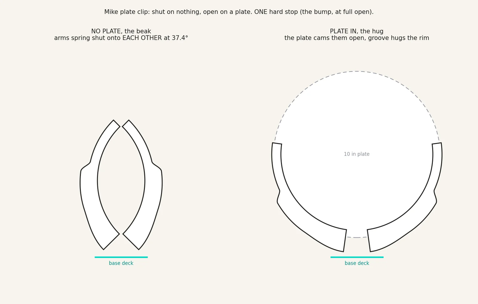
The part was built in FORMA, our own parametric CAD engine. That means the clip is held as a set of driven numbers, not as geometry someone pushed into shape: the arm's outer radius, the groove that takes the plate rim, the spring's free angle, the deck height. Change one and every face that depends on it re-solves.
This is the part people mean when they say AI sped it up, and it is worth being precise about. Nothing invented the part. A person decided what it had to do and checked every solid that came out. What the engine bought was the ability to answer "what if the arm were 10 mm shorter" in the time it takes to run it, which is why the revision below landed in hours.
The Measurement
The listing was wrong, and the calipers found it.
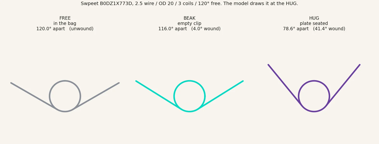
The clip needs two torsion springs. The listing gave an outside diameter of 20 mm and a leg length of 50 mm. Measured on the bench with calipers, the real spring is OD 20.10, ID 15.10, body 10.10 not 8.20, and legs about 30.5 mm, not 50.
That is not a rounding error. A twenty-millimetre difference in leg length made the through-hole base pocket the first design used physically impossible, and both spring seats had to be rebuilt around the part that actually arrived. Had it gone to print on the listing's numbers, the first the customer would have known about it is a clip that would not close.
Printed Here
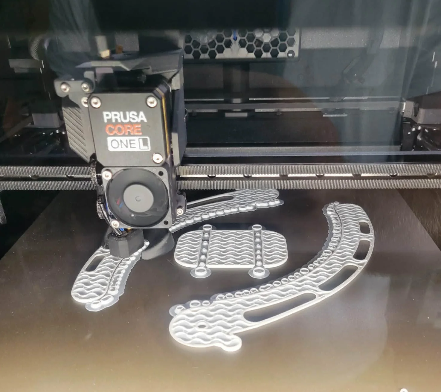
On the plate, in ASA.
ASA, not PETG. A dishwasher's sanitize cycle runs past the point where PETG starts to soften, and a clip that relaxes on the hot cycle is a clip that drops a plate. It is the kind of choice that never shows up in a photograph and decides whether the part survives its first month.
The Test Fit
He printed it, fitted it, and drew on it.
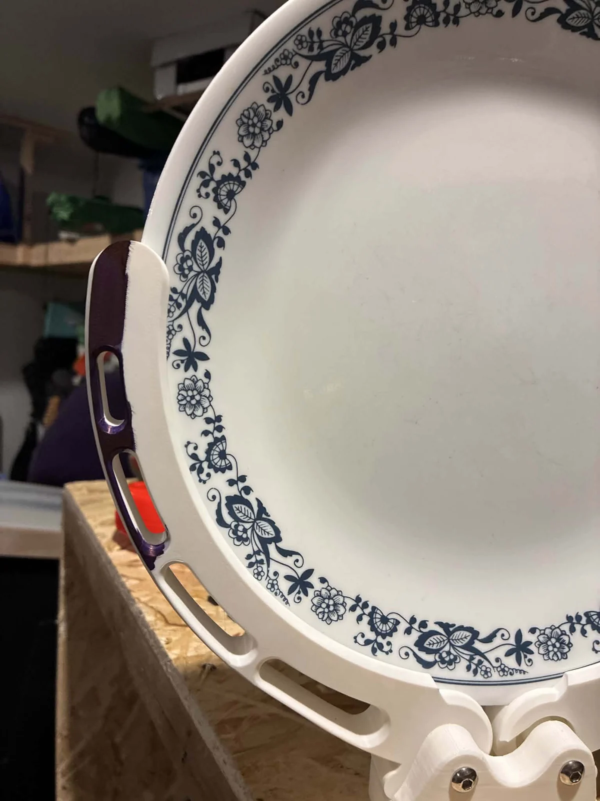
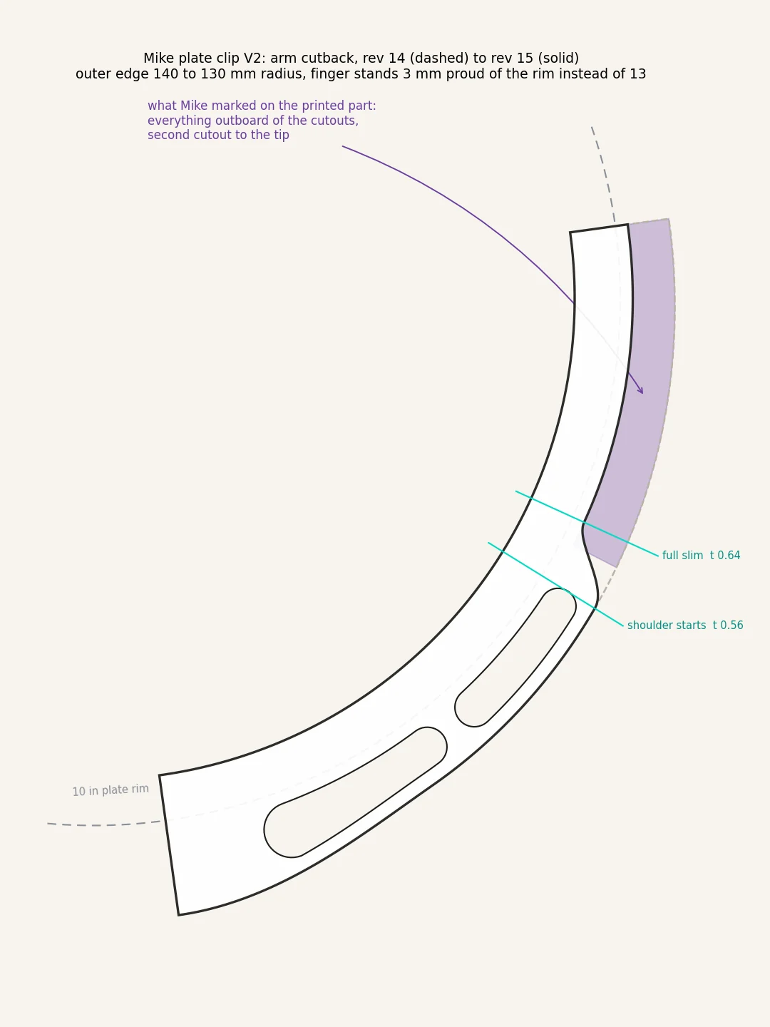
The revision before last went to the customer as a fit test. He put it in the rack, said the plate fit was good, and then marked the printed arm with a marker to show exactly what had to come off. Then he photographed it and sent the photograph back.
That mark was not eyeballed into the next version. The marker was isolated by hue in the photograph and the plate rim fitted as a circle to give it scale, so the cut came back as numbers: from the second cutout to the tip, and across the arm from radius 136.5 down to 128.0. The blade's whole outer band came off above the second cutout, and the groove that holds the plate stayed.
The Revision
Three millimetres instead of thirteen.
The cutback went in as a third taper stage, outer radius 140 down to 130, faired into the shoulder and held flat to the tip. The top two windows went with it, four down to two. The finger now stands 3.0 mm proud of the plate rim instead of 13.0, which is the side-by-side clearance he was after.
One knock-on had to be tracked rather than assumed: the tips meet to form the beak, so shrinking the blade shrank the tip cap and the arms close 0.43 degrees further than before. The rest angle moved from 37.00 to 37.43 degrees, re-measured off the built solids rather than carried forward from the old model. Coil stress came out at 1109 against an 1178 allowable.
Delivered
Printed, fitted, and no further revisions.
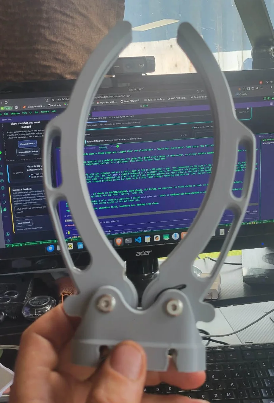
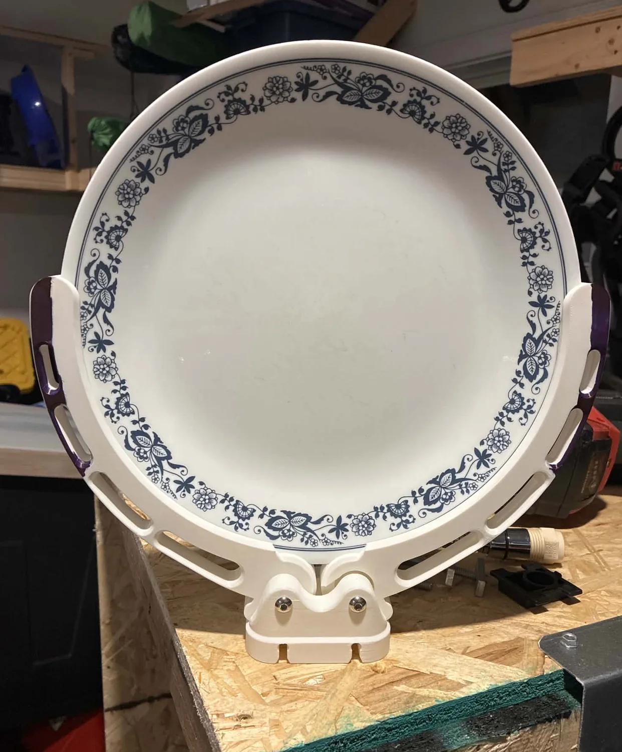
Revision 15c went out on 12 August. It was printed, fitted, and that was the end of it: no further changes were asked for. Twenty-two days from the enquiry landing, of which about a week was lost to a house move at this end.
What You Keep
You leave owning the design.
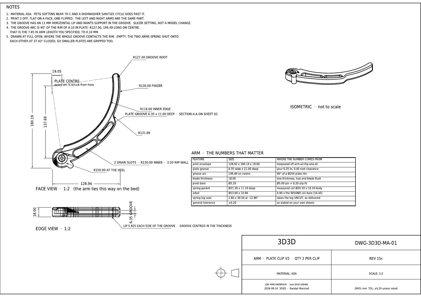
When this job finished, the customer had the STEP files, the STL files and the full blueprint package handed back to him. Not a photograph of a part and an invoice: the design itself.
That is the difference between buying a part and having one made. He can reprint it, resize it for an eight-inch plate, hand it to a machine shop, or have somebody else make a thousand of them, and none of that needs our permission or our involvement. A part without its files is a part you have to come back for. This one is not.
The drawing package is generated from the delivered STEP file rather than drawn by hand afterwards, so the views are real projections of the solid that shipped. A gate runs 48 checks against that solid before anything is exported. All 48 passed.
The Pipeline
Six steps, every time.
You send what you have
A photo, a sketch, a measurement, or the broken piece. This job started with one picture and the words 'an idea'. Eight messages the same morning settled what it had to do.
It becomes a model with numbers in it
Built in FORMA as driven dimensions, not a drawing. Every face, radius and clearance is a value we can change and re-run, which is the whole reason a revision takes hours.
The physical parts get measured, not trusted
The spring's listing was wrong by 20 mm on the leg and silent about the body. Calipers found it before the first print did, and it changed the base entirely.
You print it and tell us what is wrong
A test-fit revision goes out. On this job the customer fitted it, marked the printed part with a marker to show what had to come off, and photographed it.
The fix is measured off your mark
The marker was isolated by hue and the plate rim fitted for scale, so the cut came off the photograph as a number rather than a guess. The finger ended up standing 3.0 mm proud of the plate rim instead of 13.0.
You leave owning the design
STEP files, STL files and the blueprint package, handed to you. Reprint it, resize it, or take it to any shop in the world. A gate runs 48 checks against the delivered solid first, and all 48 passed on this one.
Questions
Straight answers.
I only have a photo and a rough idea. Is that enough to start?
Yes, and it is how most jobs start. The job on this page began with one picture and the words 'an idea'. A photo, a rough measurement, or the broken piece itself is enough for us to come back with a real price and a first model.
How long does a custom part take from first message to finished part?
The job on this page took 22 days from the enquiry landing to the part being printed, fitted and accepted, and about a week of that was lost to a house move. A straightforward part with no revision round is faster. You get a fixed price back inside a day, and the modelling time is quoted with it.
What happens if the first version is not right?
You print it, fit it, and tell us what is wrong. On this job the customer marked the printed part with a marker to show what had to come off, photographed it, and sent it back. That mark was measured off the photograph rather than eyeballed, and the next revision was the last one.
Do I get the files and the drawings?
You own them. When this job finished the customer had the STEP files, the STL files and the full blueprint package handed back to him, not just the printed parts. That is the point of working this way: you leave with the design, so you can reprint it, resize it, or take it to any shop in the world without coming back to us for permission.
What does AI actually do in this process?
FORMA, our own parametric CAD engine, holds the part as a set of driven dimensions rather than as a drawing. Changing a spring's free angle or an arm's outer radius is a re-run, not a re-model, which is why a revision lands in hours instead of days. It does not invent the part. A person decides what the part has to do and checks every solid that comes out.